The assembly is quite simple. The following pictures show the assembly in detail.
Pimoroni Hyperpixel 4.0 Square Touch Display and enclosure with cable parts.
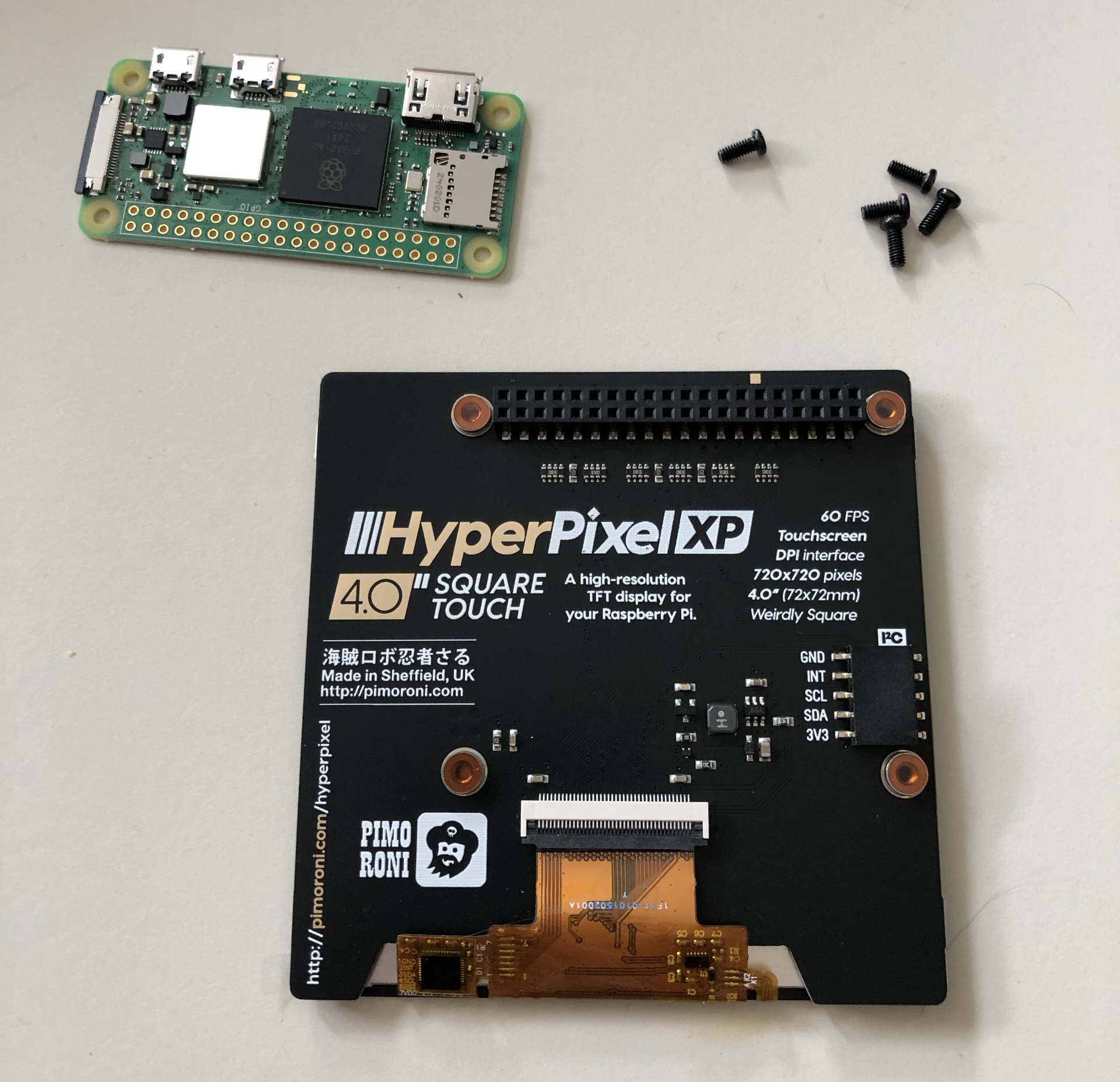
Scope of delivery of the Pimoroni Hyperpixel Display (with screws and spacers).
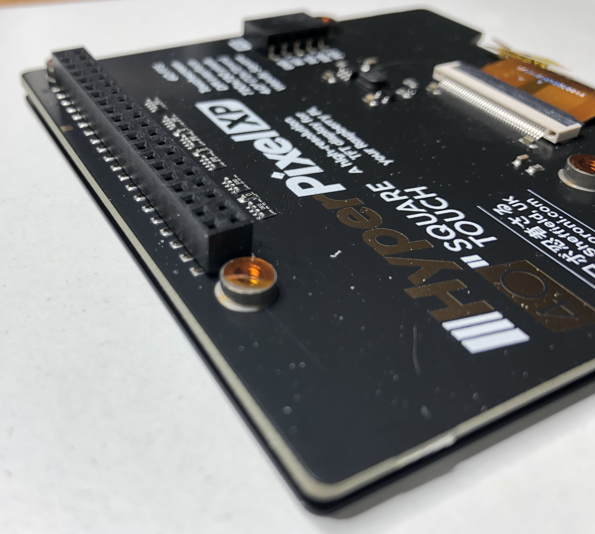
Pimoroni Hyperpixel backside with mounting accessories.
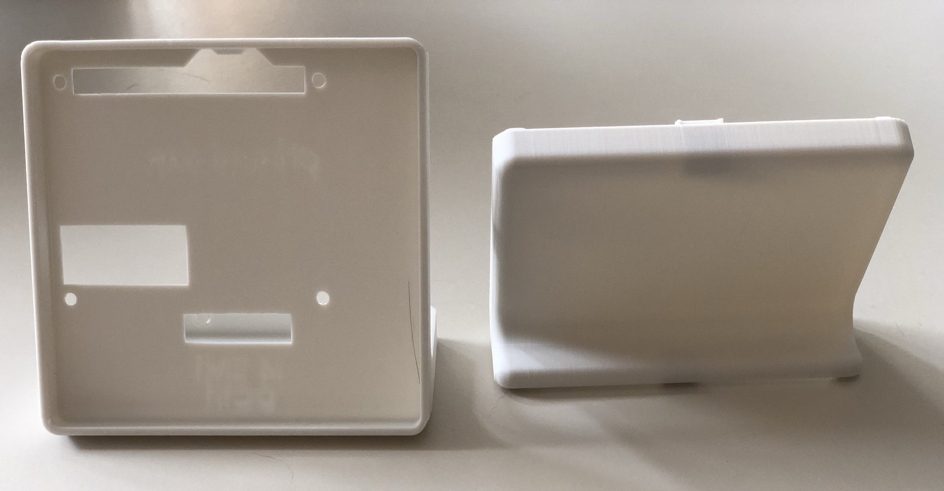
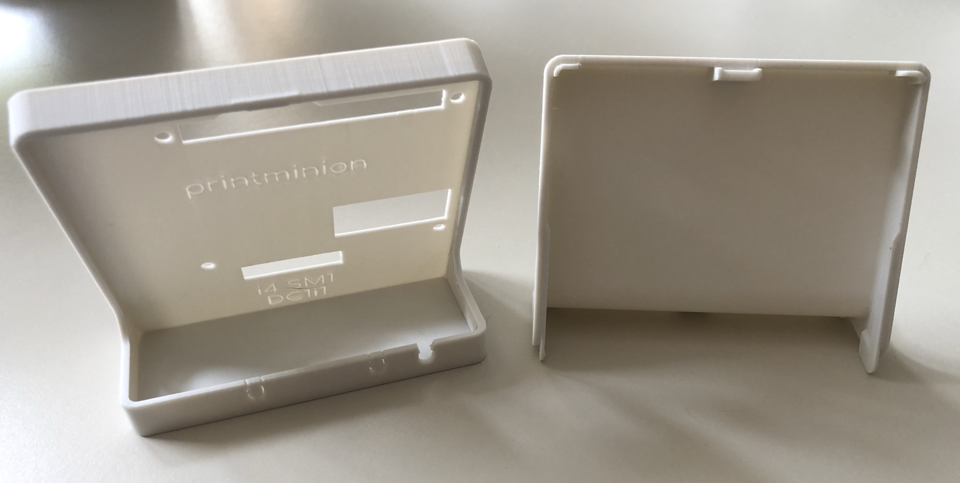
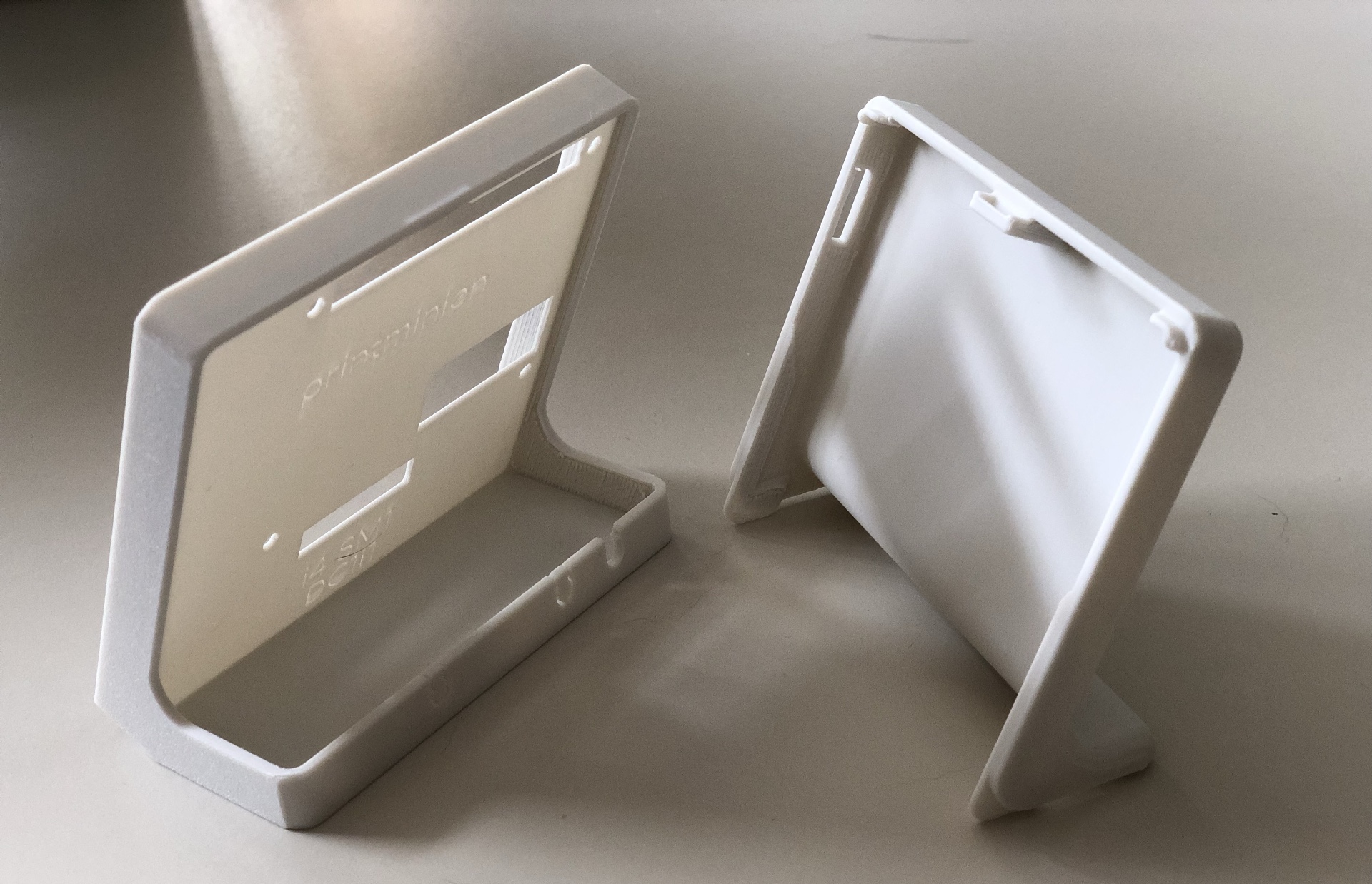
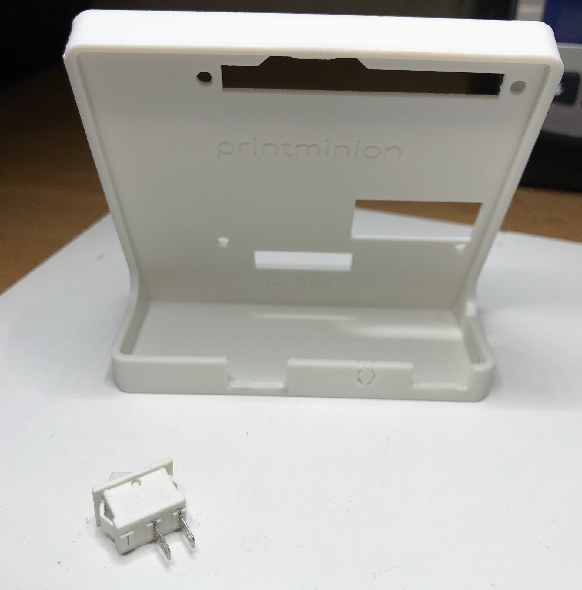
Enclosure parts front view.
Enclosure parts back.
Enclosure parts side view.
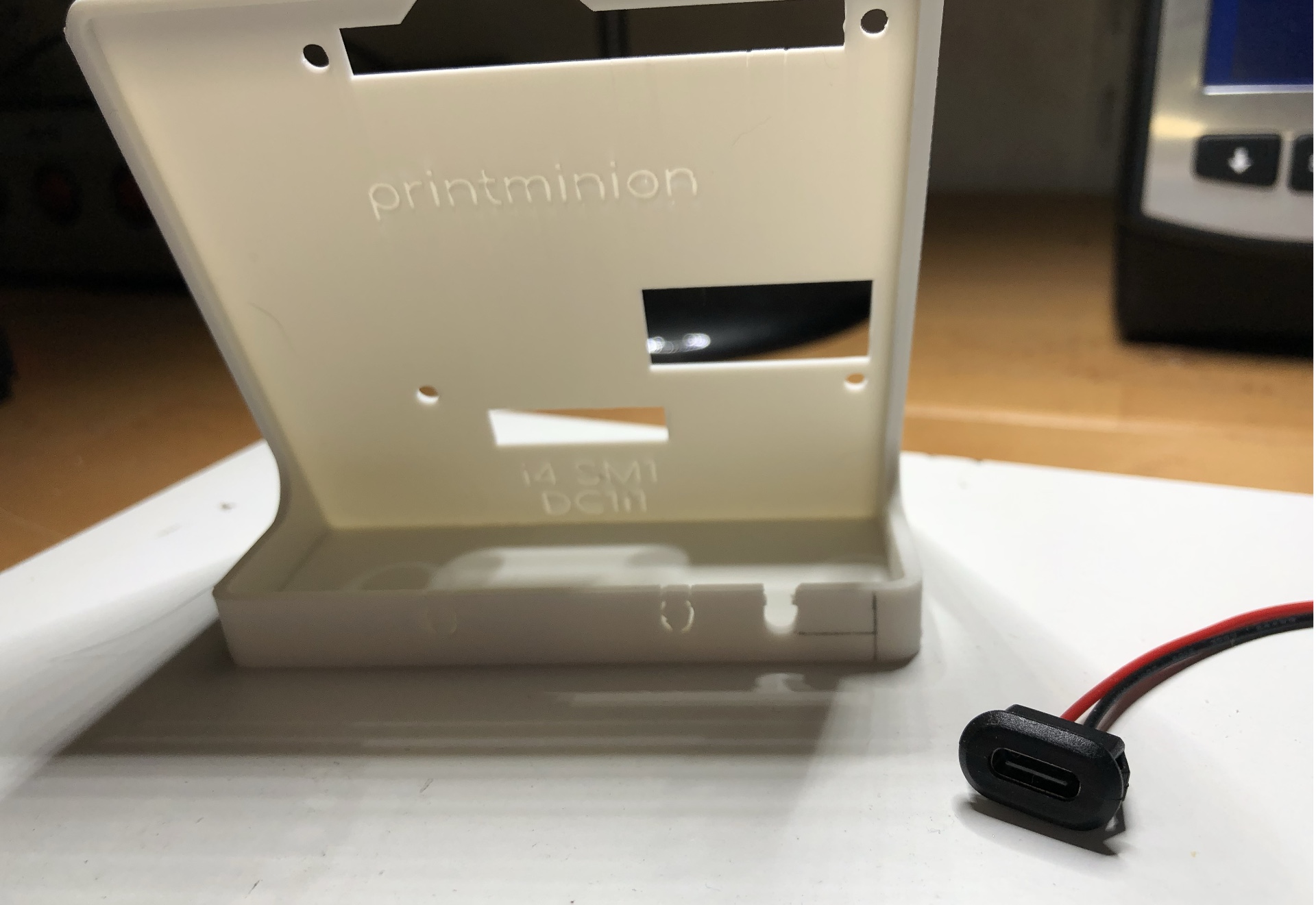
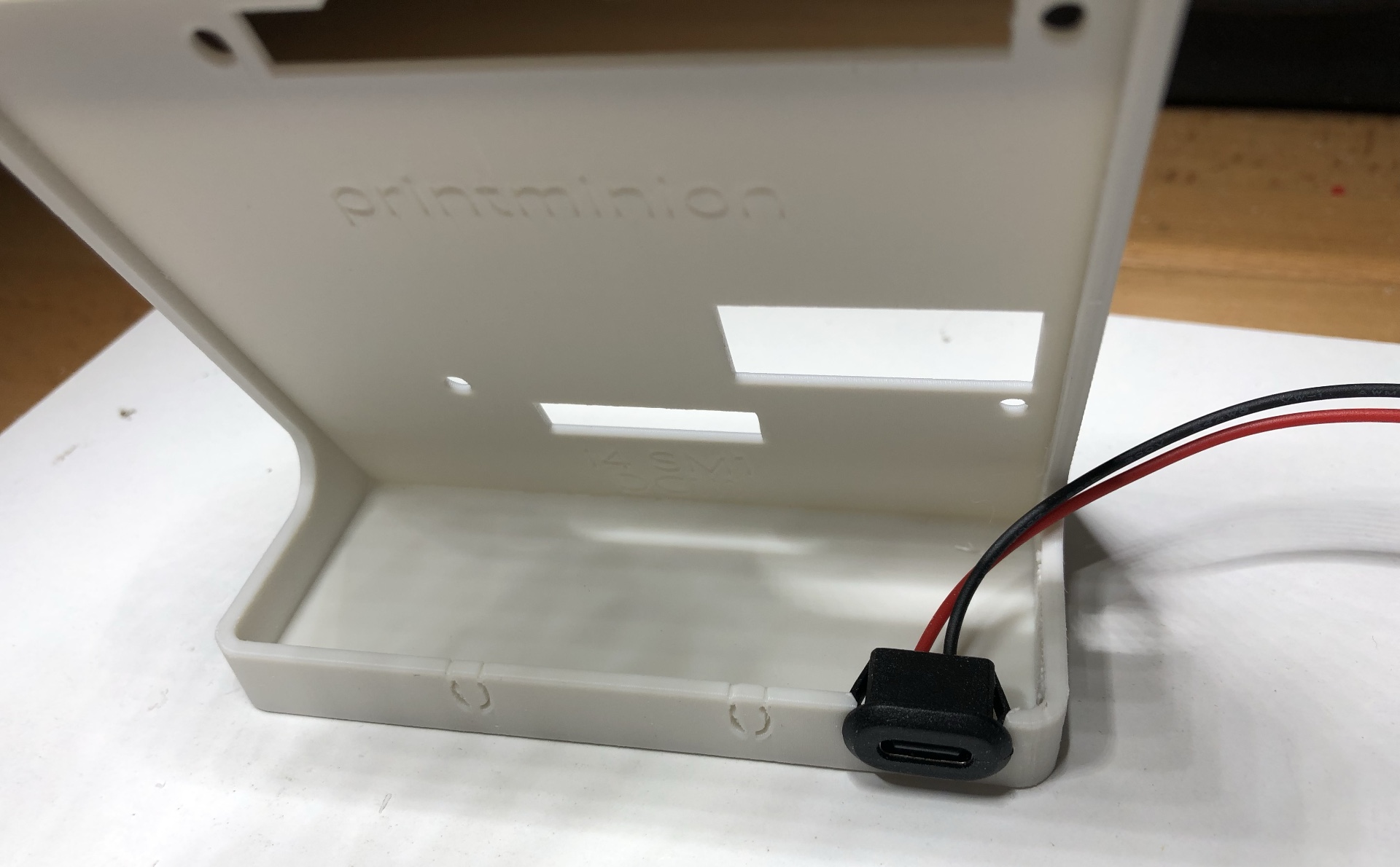
Enclosure with USB-C connector.
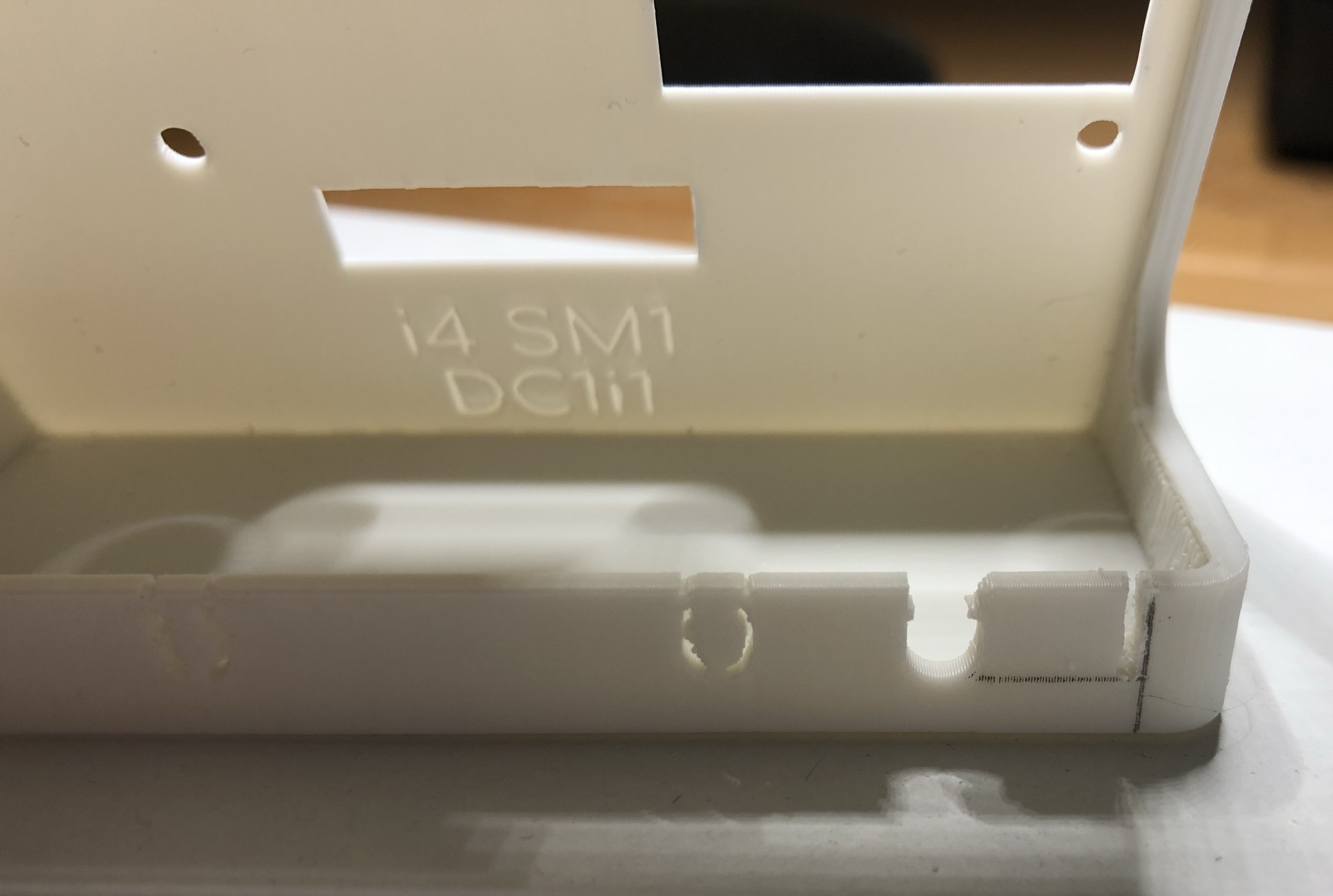
Enclosure with saw marking for USB-C power connection socket.
Enclosure with inserted USB-C connector socket.
Enclosure with saw marking for power switch.
Enclosure with outbreaks for power switch and USB-C power connection socket.
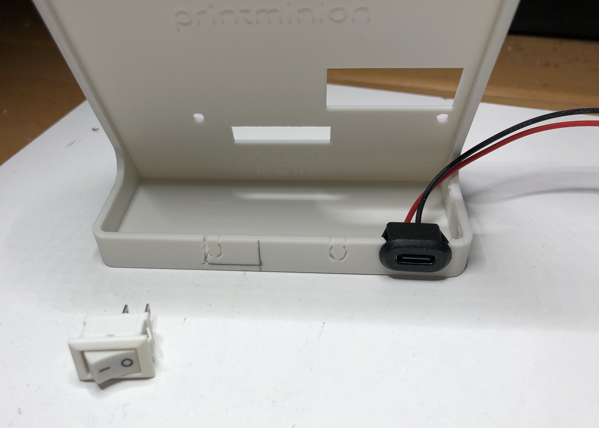
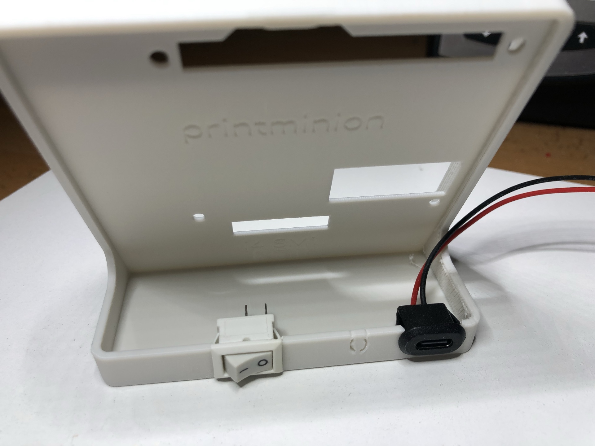
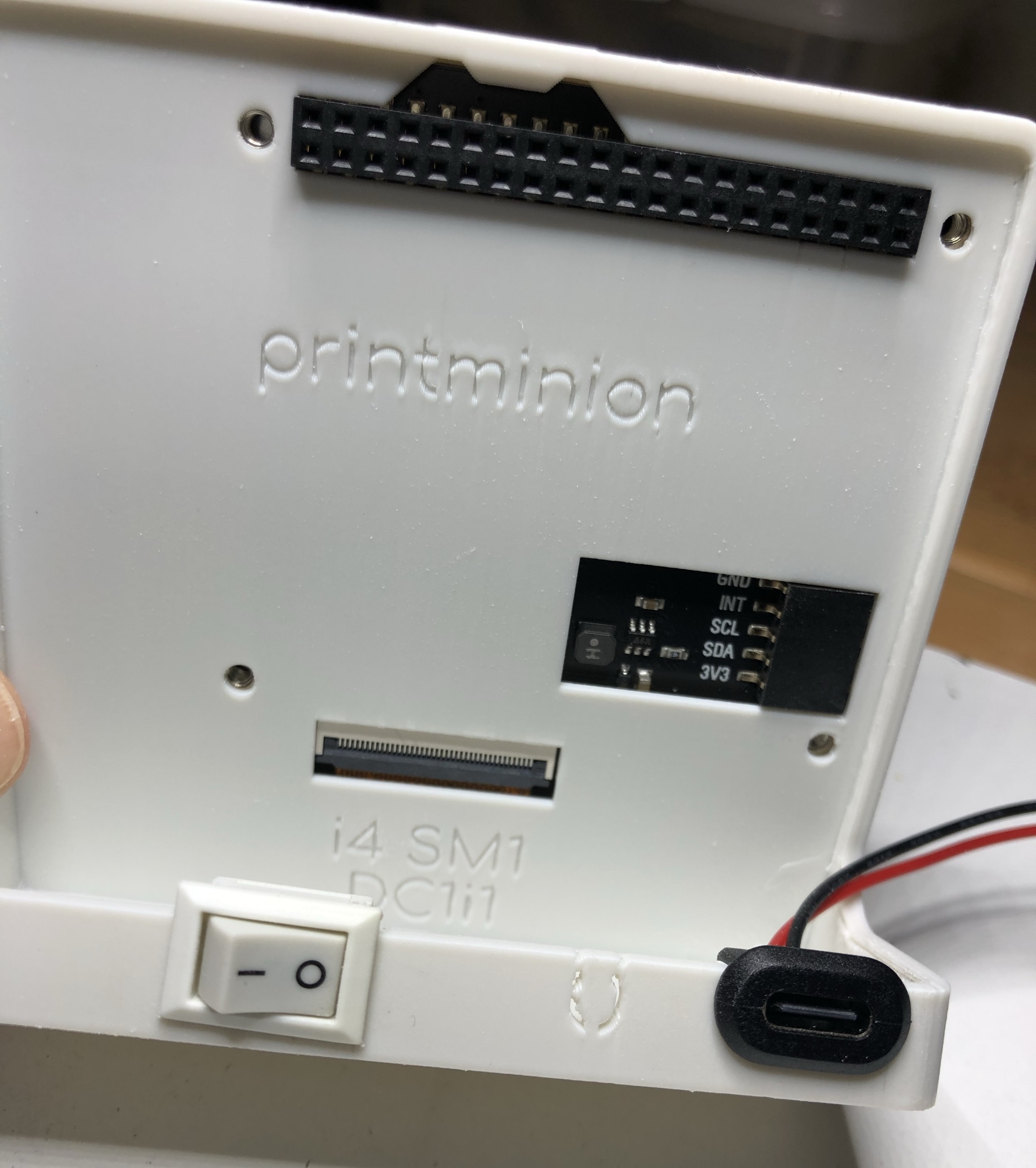
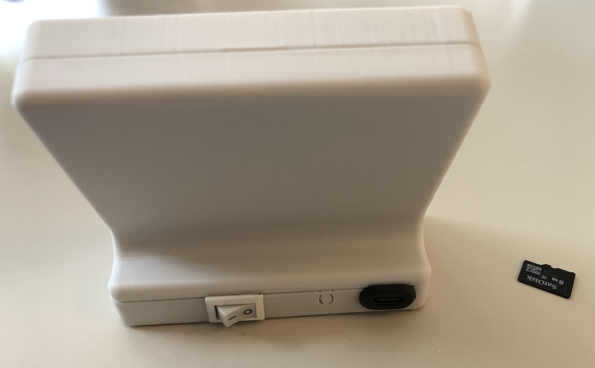
Enclosure with inserted power switch and USB-C power connection socket.
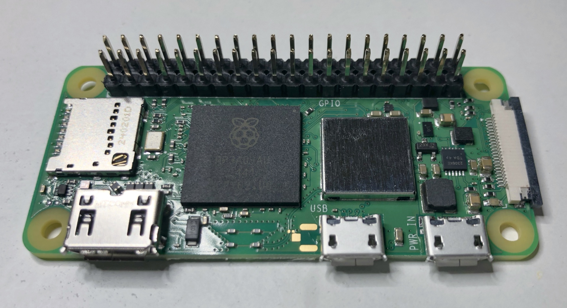
Display and Raspberry Zero 2W before installation.
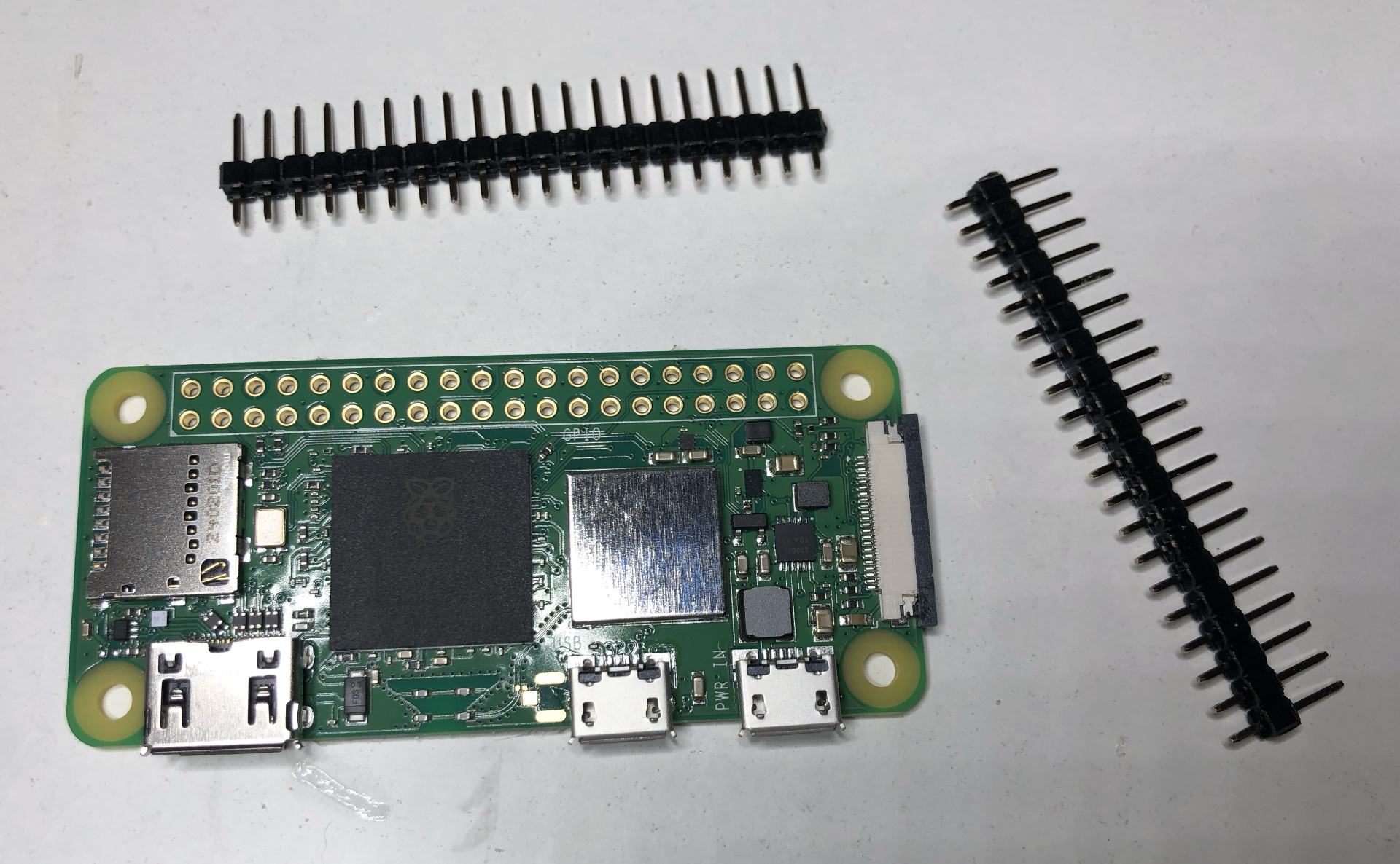
Raspberry Zero 2W with I/O male connector strips before the soldering.
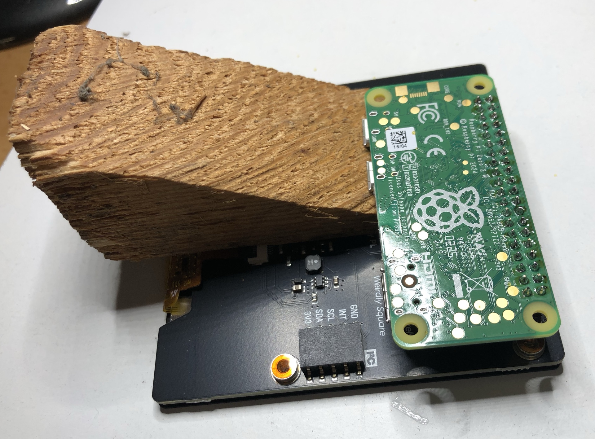
Soldering of the male connector strips with the Raspberry Zero 2W.
Raspberry Zero 2W with soldered I/O male connector.
I/O connection of the display.
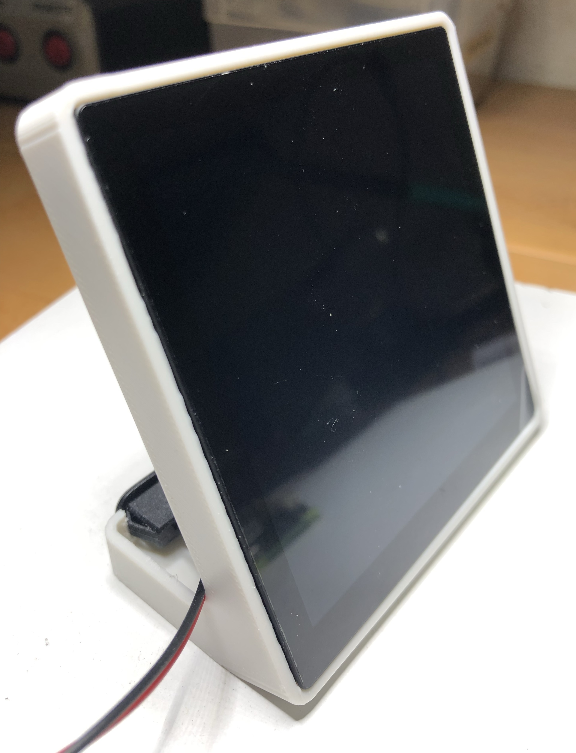
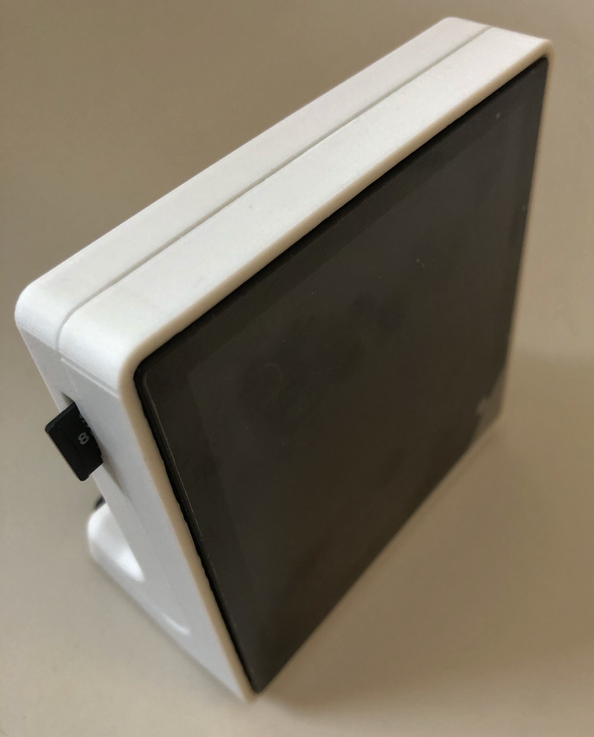
Front view of the enclosure with inserted display.
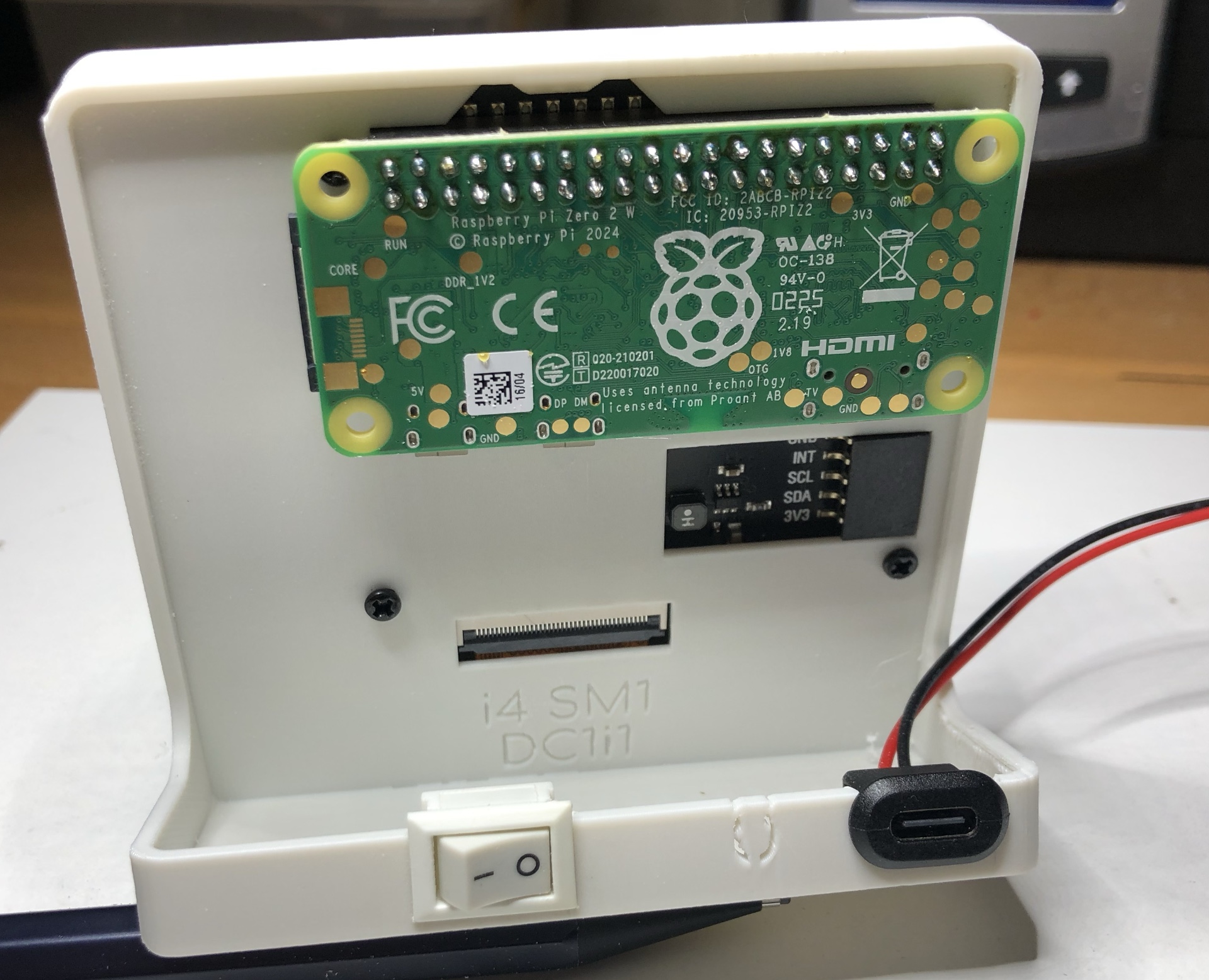
Open back of the enclosure with inserted display.
Place Raspberry Zero 2W in the I/O port and press.
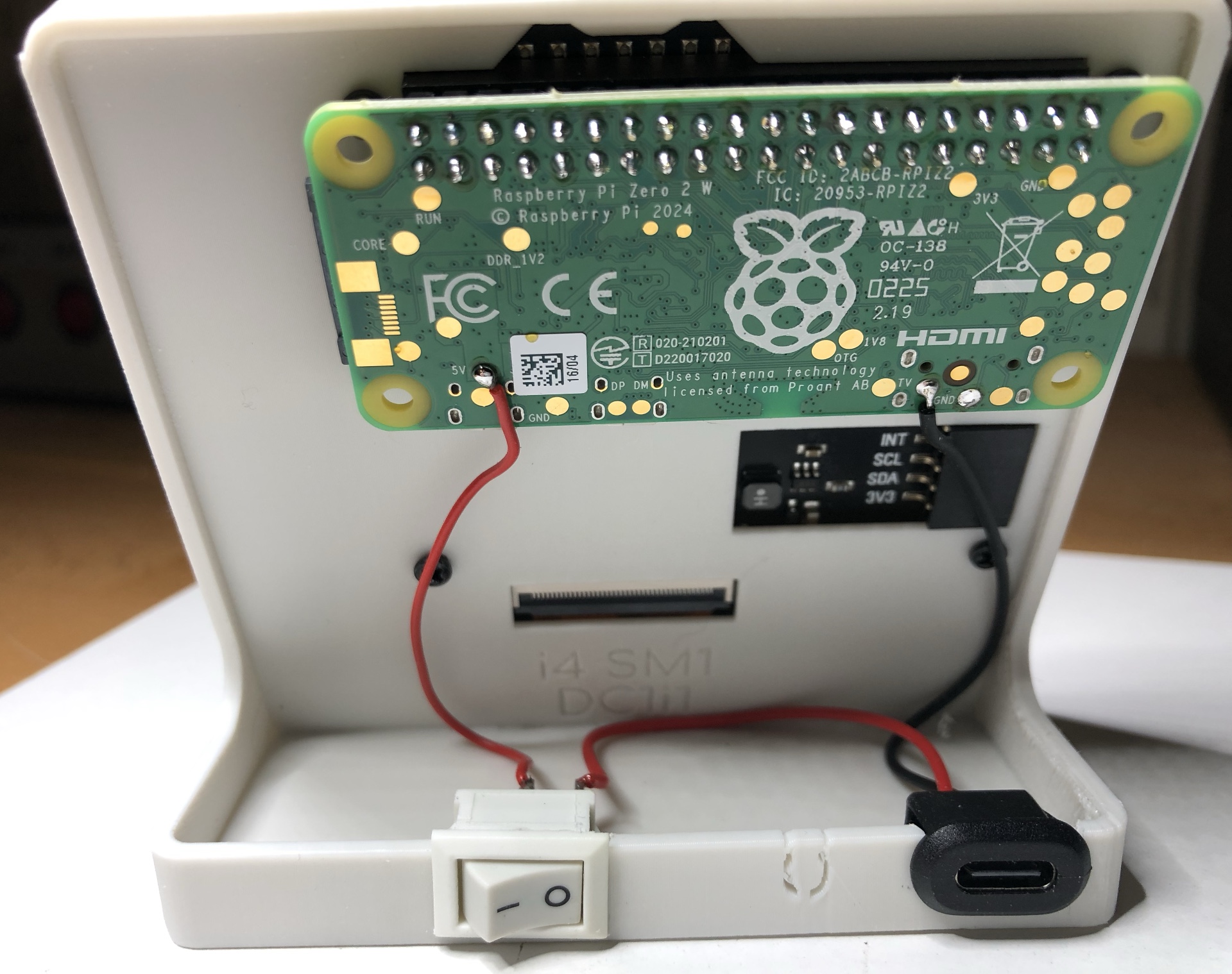
Connect power supply cables with switch and USB-C power supply connector (soldering).
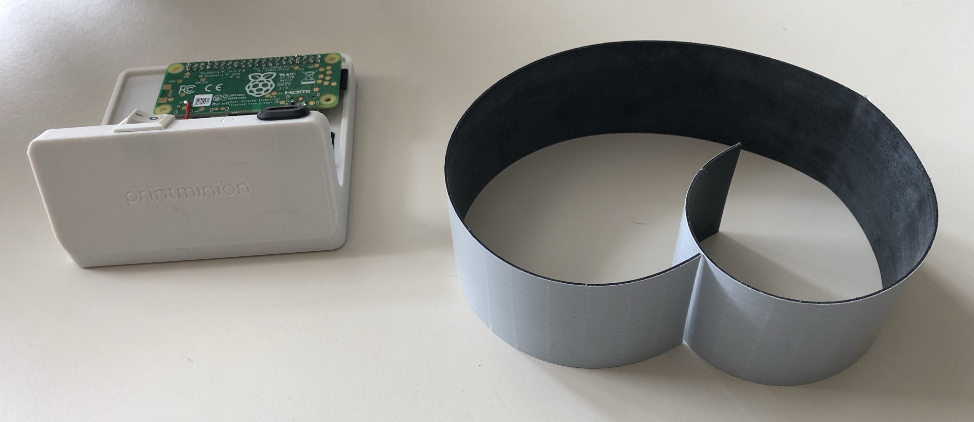
Bottom side of the enclosure and thin self -adhesive rubber strip.
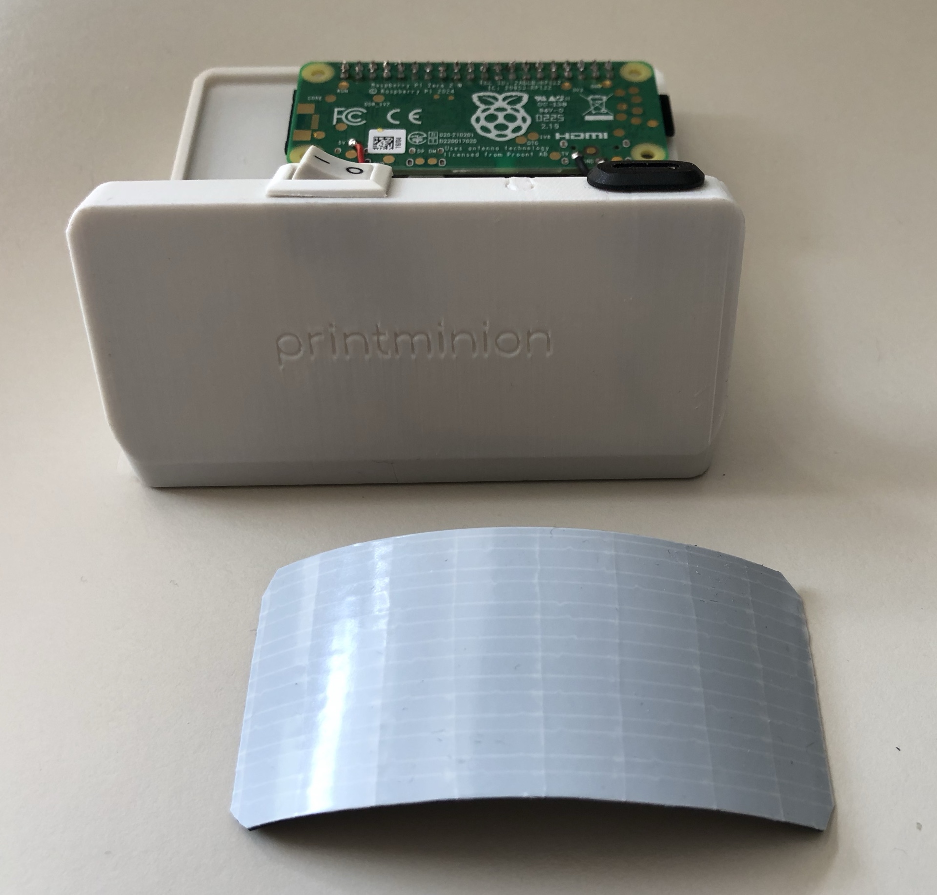
The rubber strip was trimmed to fit.
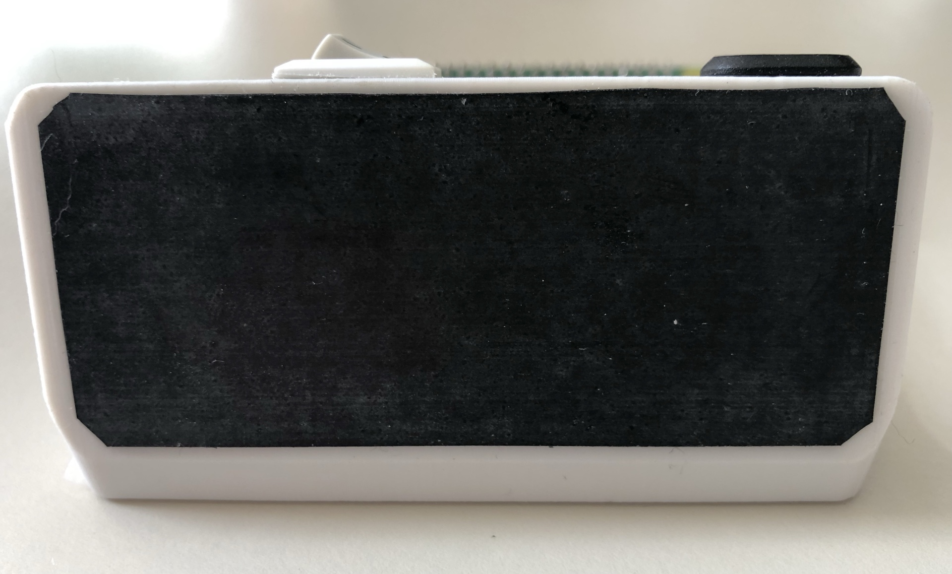
The rubber strip is glued to the bottom side of the enclosure.
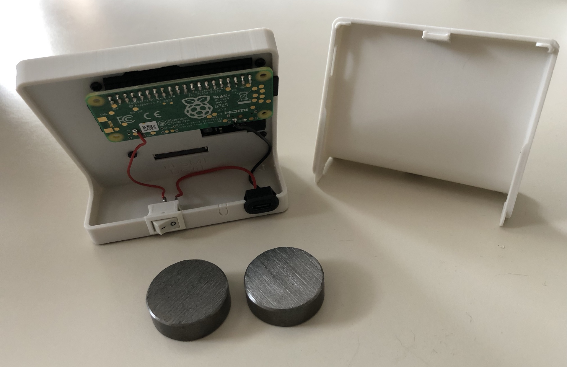
Open enclosure and 2 heavy round iron weights. The installation of the weights is optionally intended as a balancing weight for the Powerbank.
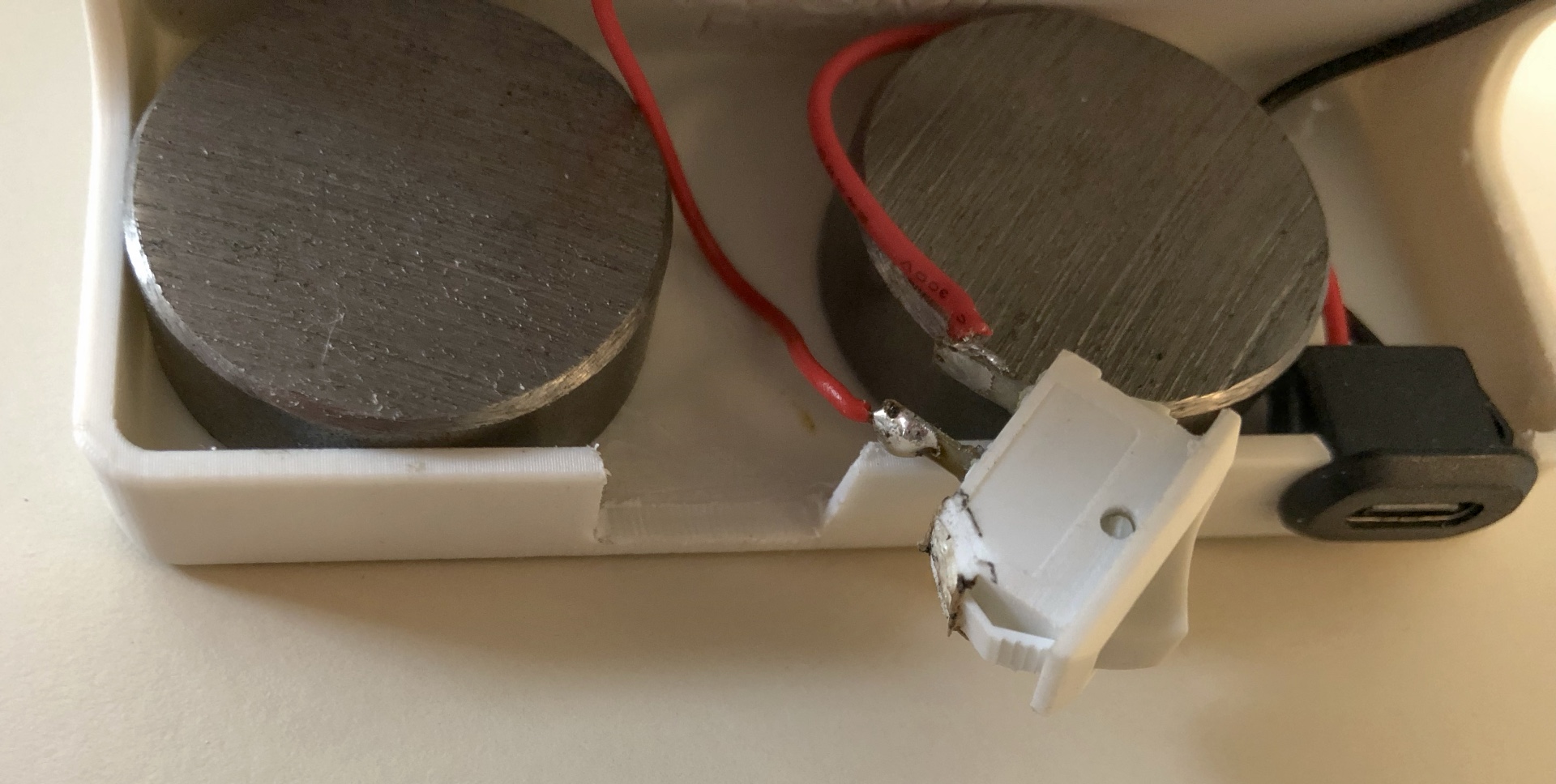
In order for the left weight to fit into the case, the left corner of the switch must be 'desoldered' or sawn off.
The weights give the enclosure the necessary weight to prevent it from tipping over due to the power bank which is pressed-on to the backside.
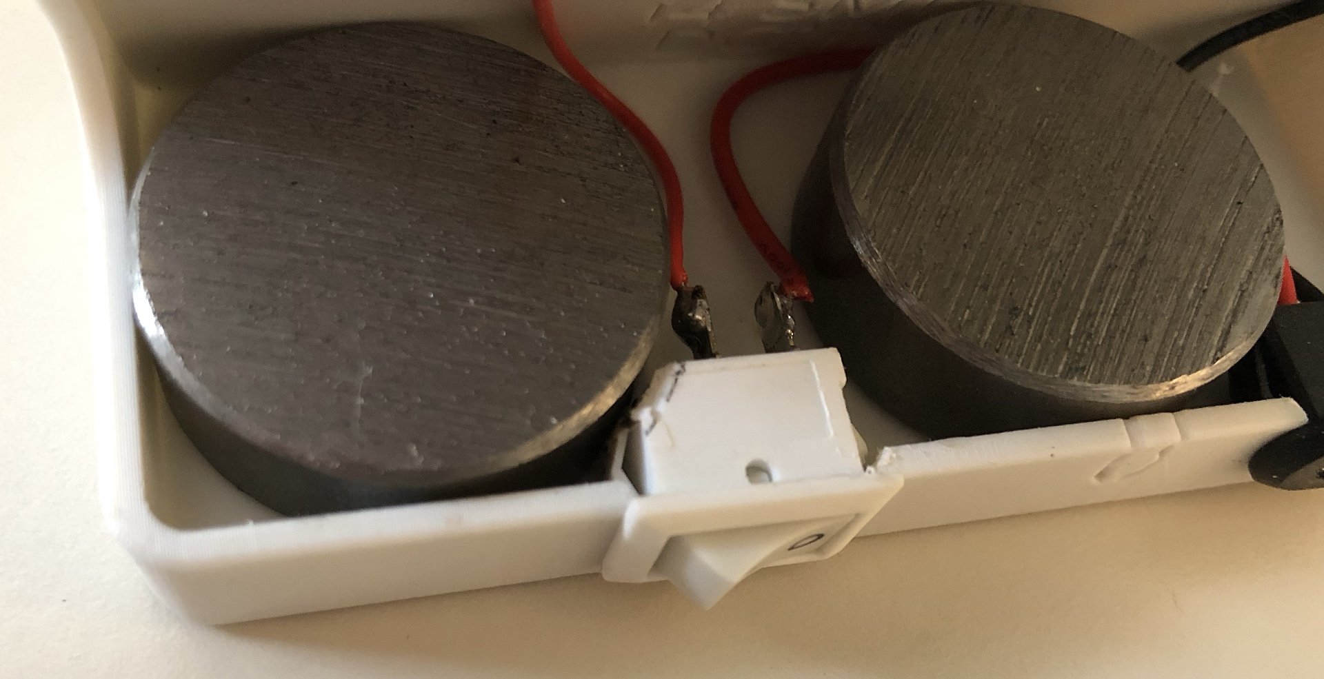
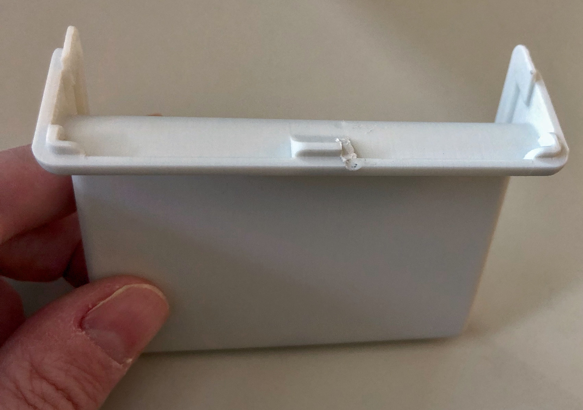
To ensure that the enclosure with the weights can still be closed, part of the snap-in bracket of the rear housing must be shortened.
The two enclosure parts are pressed together and then will snap-in.
The enclosure with half inserted micro SD card.
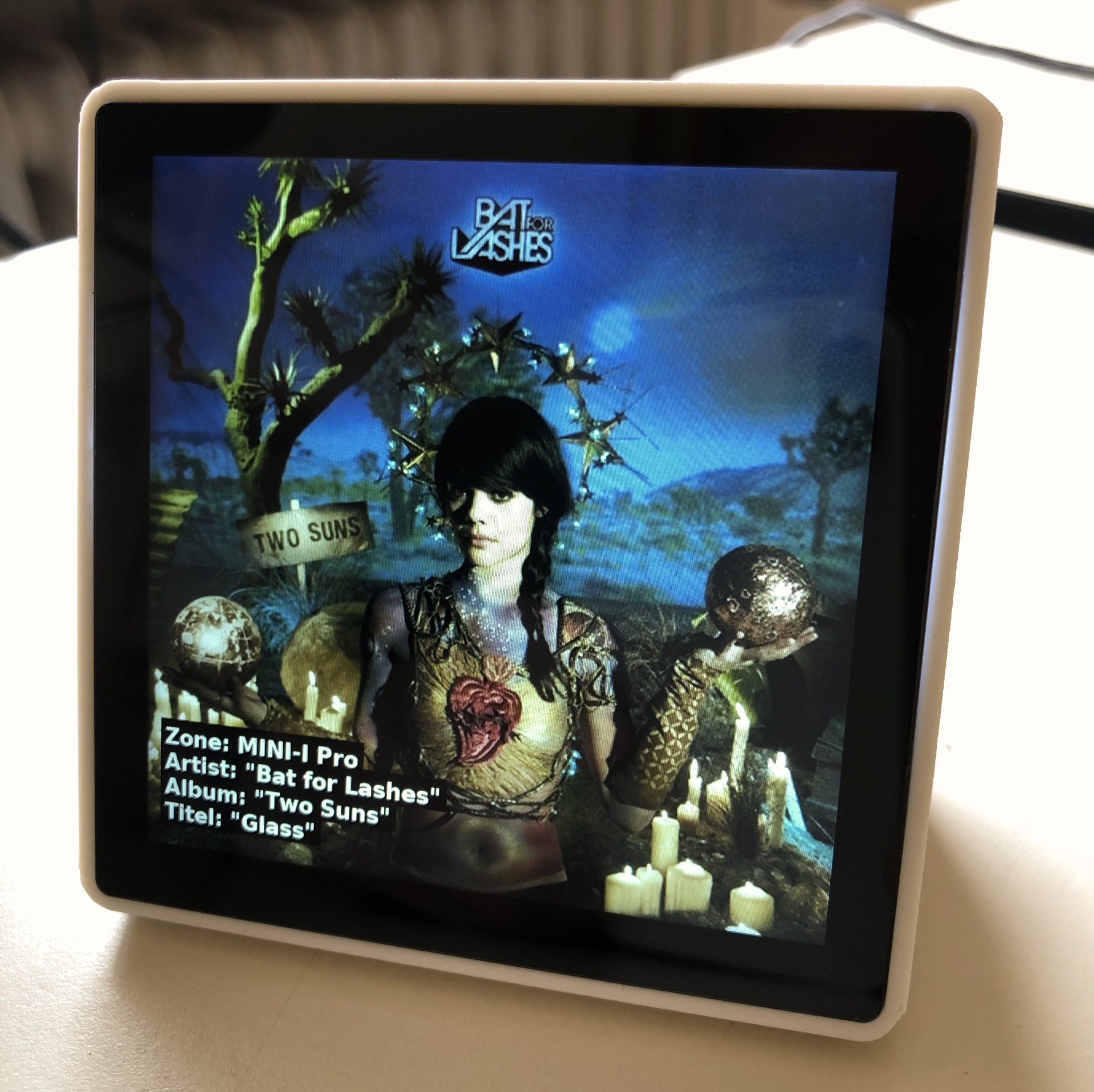
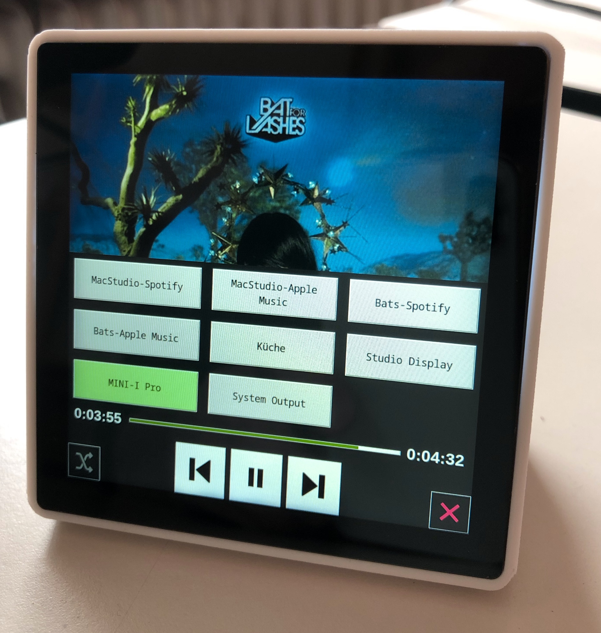
The Coverplayer shows a cover with title information.
If you tap on the cover, a menu appears with buttons for zone selection and play control as well as playing time information.
Optional power bank
Optionally, the Coverplayer can be operated with a power bank as a power source. This lasts for many hours up to a whole day or more. The runtime depends on whether the display is always on or goes into sleep mode after an adjustable time. If you tap the display, it comes back on again. If you invite the display, it will be all the time. To prevent the display from tipping due to the weight of the power bank, we have built the two weights into the display as described above. If you do this option not Need, then you can do without the weights and the steps described in the further.
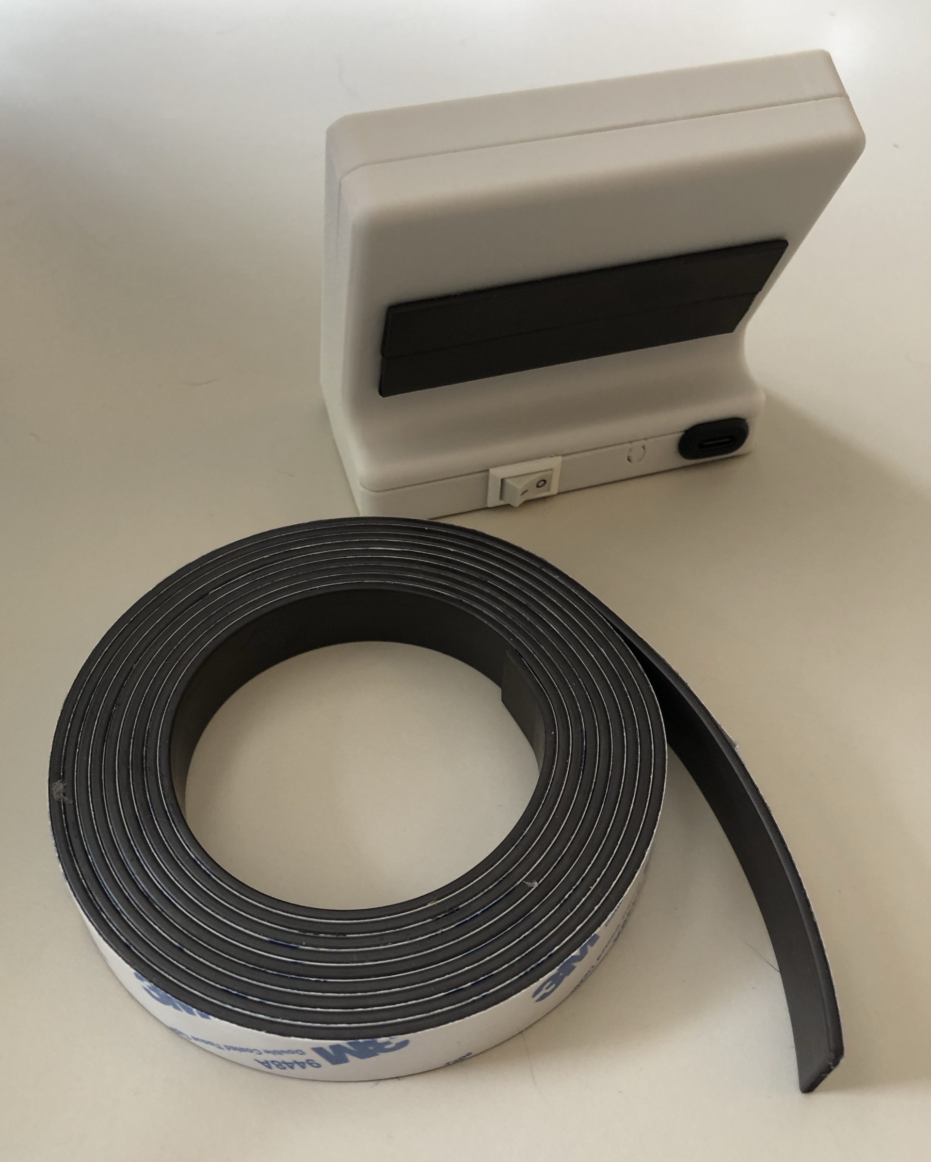
Enclosure with self -adhesive magnetic strips on the back.
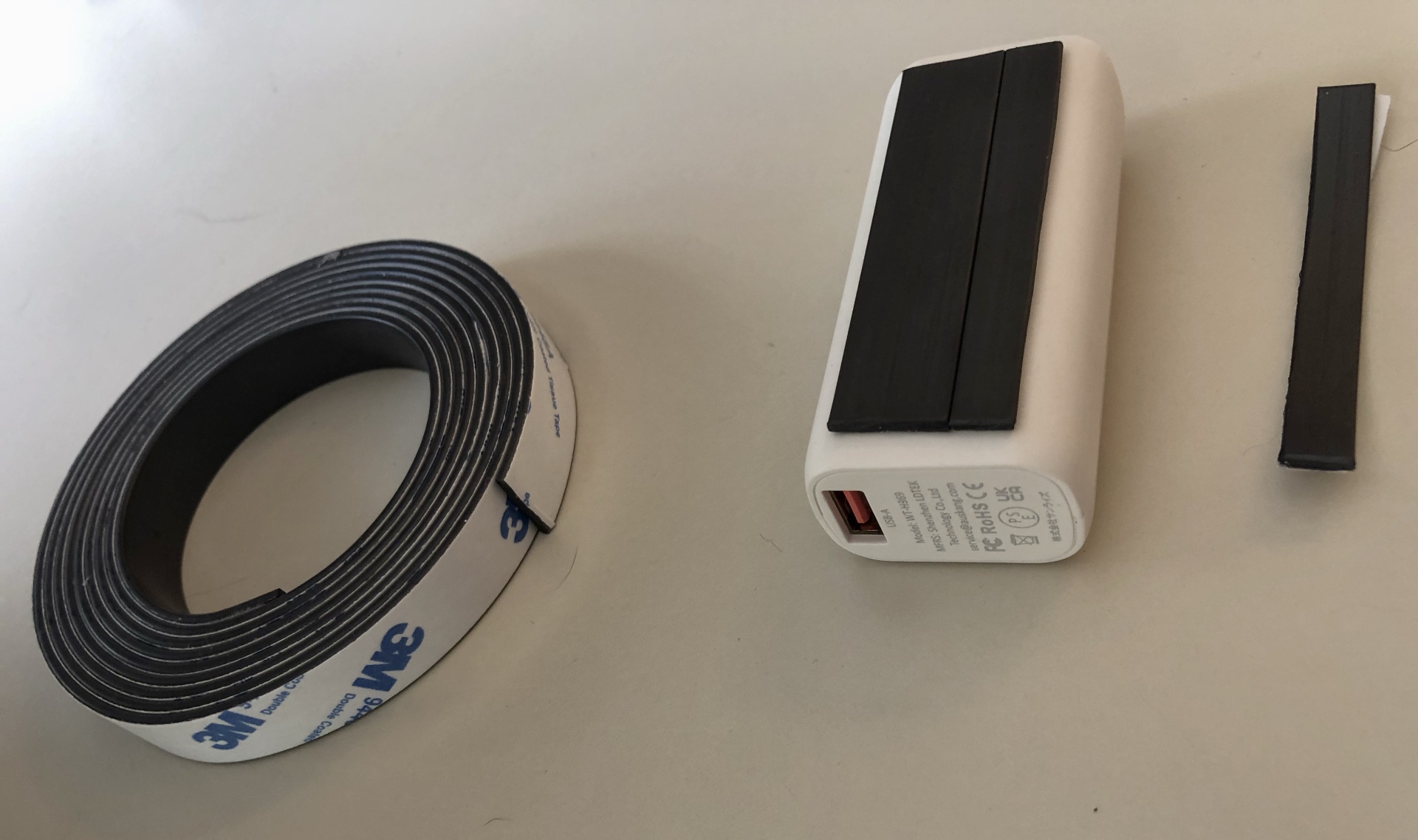
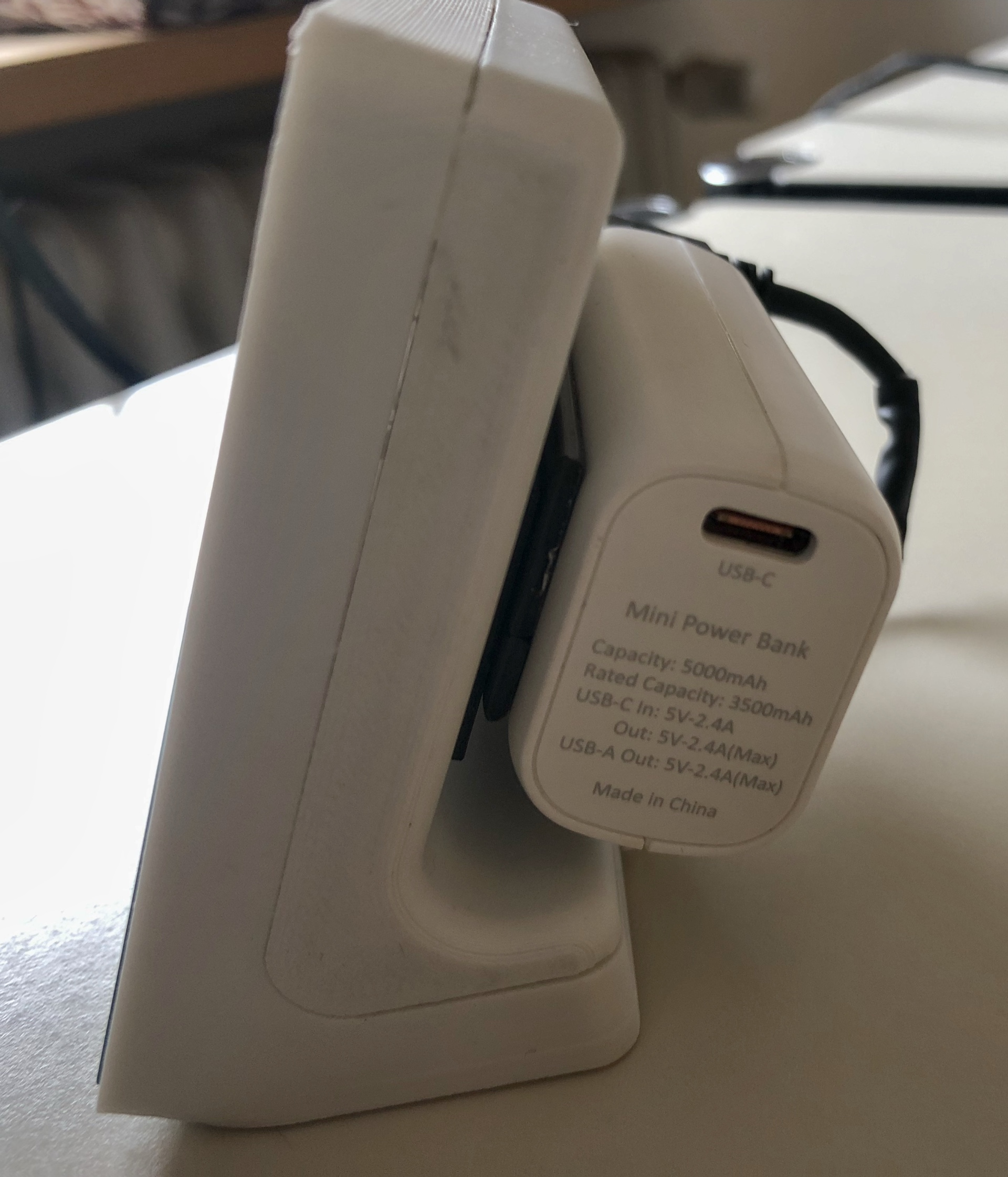
Power bank with self -adhesive magnetic strips on the back.
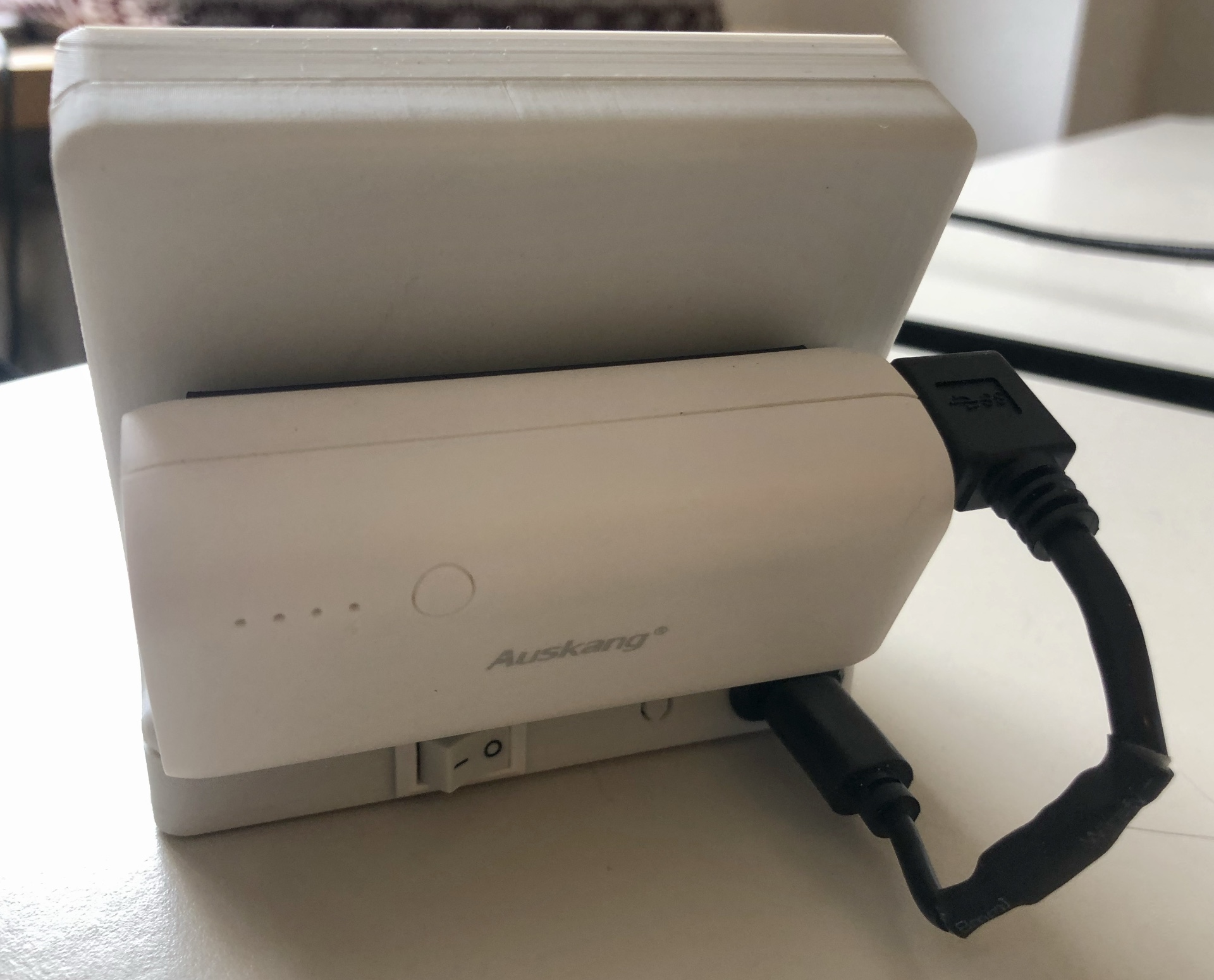
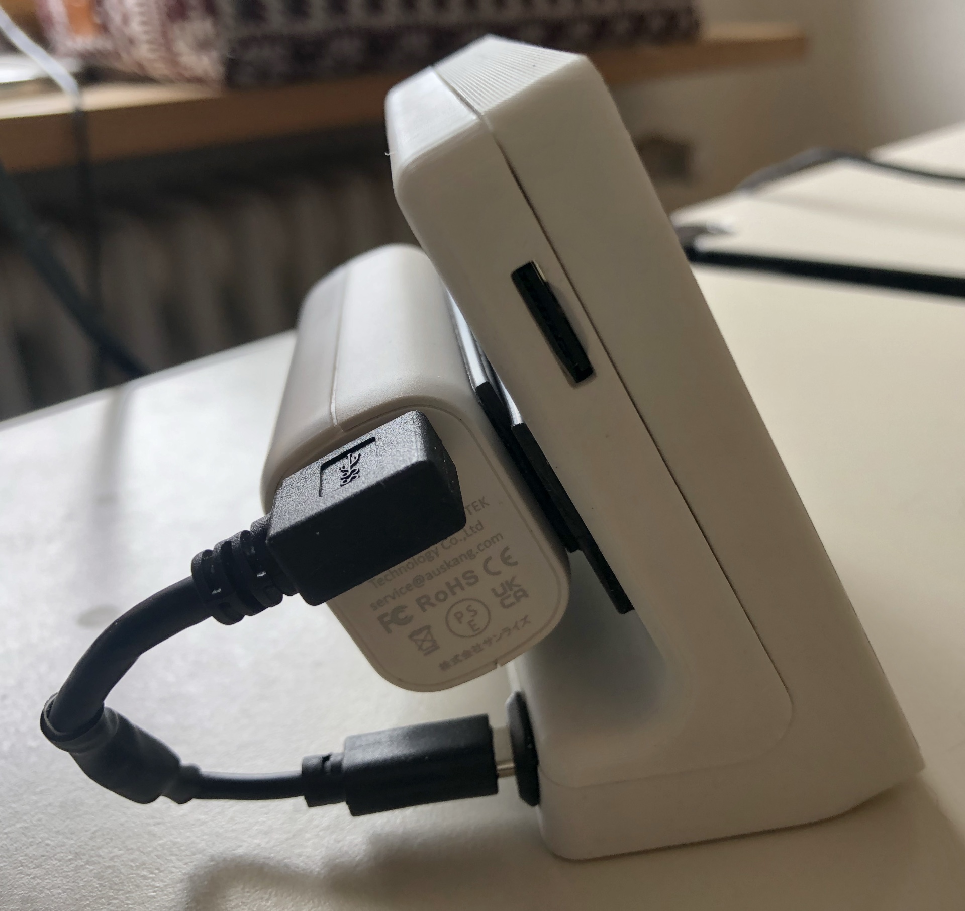
The power bank is connected to the case magnetically and wired with the power cable.
This is the view from the left of the enclosure with micro SD card slot and power connection cable.
This is the view from the right to the enclosure and USB-C charging cable connection of the power bank.
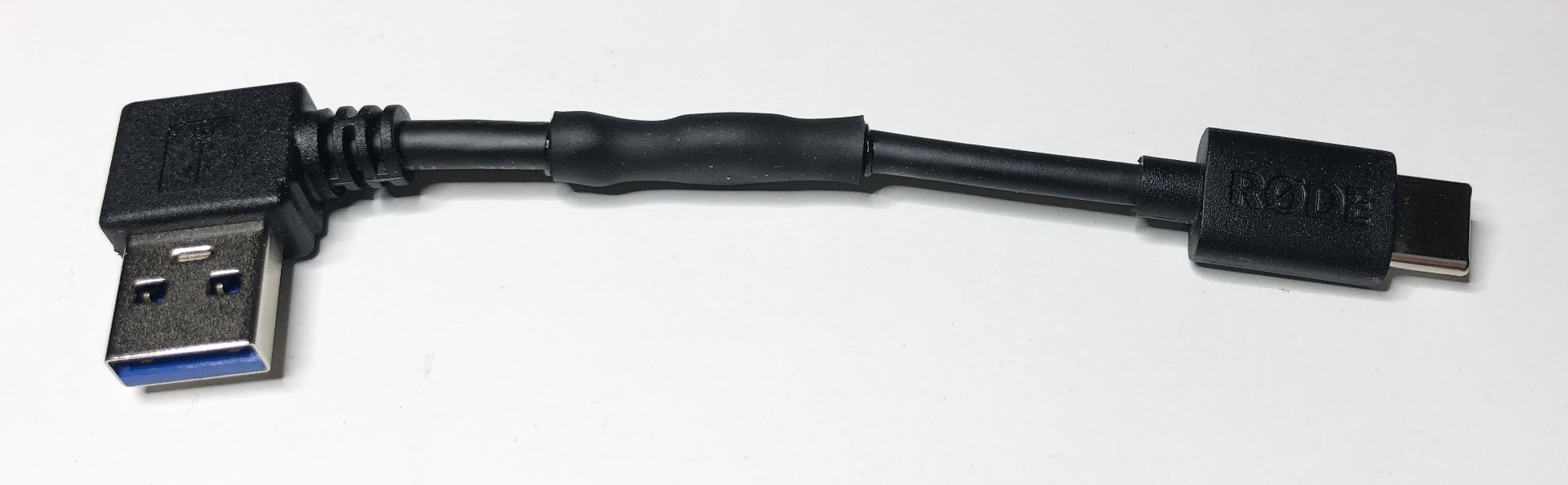
The power cable (USB-C to USB-A) is available to buy ready-made, but probably not in the optimal, short length.
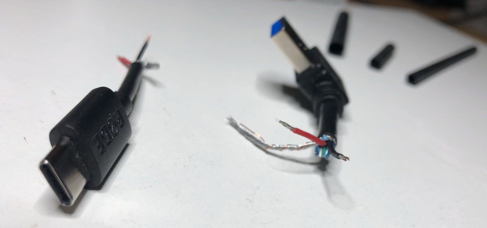
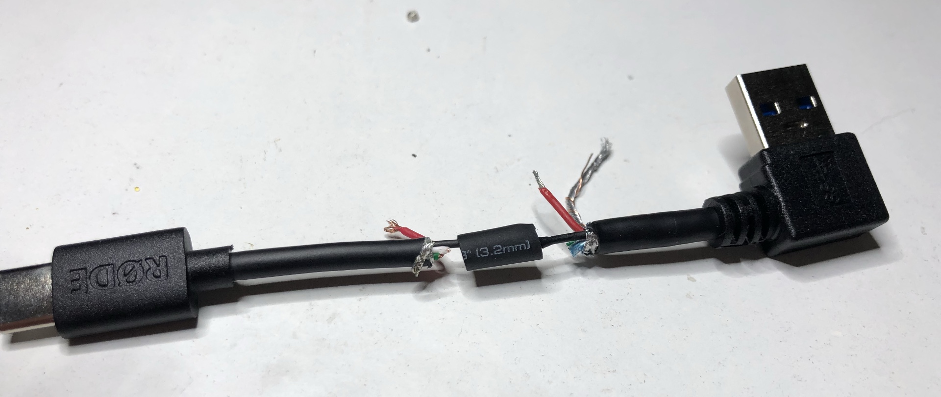
However, you can also simply solder it together from two cables, as I have done here. In addition to a USB-A and USB-C cable, you also need some heat shrink tubing and a hot air gun. A candle lighter will also do the trick. You can simply solve this from two cables, as I did here. In addition to a USB-A and USB-C cable, you also need some heat shrink tubing, as well as a hot air dryer. But a candlestick is also doing it.
The two shortened cables (USB-A and USB-C).
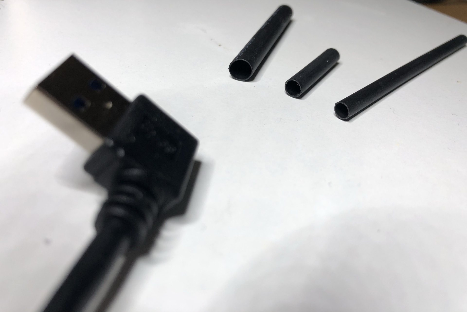
USB-A cable and some shrink tube.
First push the shrink tube over the cable end, then solder the two black cables (GND). Repeat the whole thing for the red cable (VCC).
Finally, pull the thick shrink tube over the USB-C connection into the middle of the cable and shrink with hot air.
That's all. The Coverplayer is now ready for use. I hope you enjoy to using the Coverplayer device!
 German (Germany)
  English (United Kingdom)